While designing and implementing the computer, several supporting utilities were developed. The assembler (bfasm) is responsible for translating BF programs (text) into machine language (binary), the programmer and its software are used to write data to EEPROM chips, and Mugen aids in having a more maintainable microcode definition. Each of these 3 utilities will be described in more detail below.
Assembler: bfasm
Even though the computer is designed to run BF natively, we can’t just burn any text file containing BF commands onto the program ROM and expect it to execute them. Instead, each of these commands has to be translated into its corresponding binary opcode. Table 4 lists all the available commands and the values that map to these commands. As explained in Chapter Opcodes and Control Sequences, there are a few non-BF instructions that have been added.
| Command | Opcode |
|---|---|
NOP |
0x00 |
+ |
0x01 |
- |
0x02 |
< |
0x03 |
> |
0x04 |
, |
0x05 |
. |
0x06 |
| 0x07 | |
| 0x08 | |
? |
0x09 |
PROG_START |
0x0a |
PROG_END |
0x0b |
LOAD_SLOT |
0x0c |
INIT |
0x0d |
INIT_FINISH |
0x0e |
HALT |
0x0f |
bfasm performs pretty much a one-to-one transformation of the BF commands in the provided text file into these values. It will add the preamble commands to initialize and bootload the system, as was discussed in Section Binary Format and shown in Figure 6.
Features
The bfasm utility provides the following features:
Zero Initialization
By default, only a single INIT instruction will be emitted in the preamble of the resulting binary file. This will initialize a single 256-byte block of RAM when the system boots. In practice, this proved to be enough for most programs, but if more is needed, bfasm has the option to emit an arbitrary number of INIT instructions.
Print Filenames
Especially when multiple programs are written into a single binary, it can be helpful to see what program is running after loading a slot at runtime. The -p flag tells bfasm to generate BF code that prints the source filename before it actually runs. This code precedes the HALT instruction that is inserted right before the body of the program; the filename is displayed and the user can resume the clock knowing which program will run.
Interpret ’!’ as HALT
The BF commands do not include a command to stop the program. For debugging purposes, bfasm can interpret an exclamation mark in the BF source as a HALT instruction. This can be used to set breakpoints in the BF program.
Interpret ’?’ as RAND
The Random Brainfuck Extension is supported by bfasm; when this option is enabled, each question mark in the BF source code will be assembled into a RAND instruction, which will place a random byte into the current cell (generated by the IO module).
Debug Mode
In debug-mode, each BF command is followed by a HALT instruction. This allows the user to step through the program on a command-level rather than on the cycle-level.
Echo
With the echo-mode enabled, each input-command will be followed by an output-command in order to see what’s being typed on the keyboard (if the BF program does not already do this). This feature was deprecated when the IO-module itself started to provide this facility, but was left in bfasm anyway.
Bracket Matching
The assembler will not allow programs to contain unmatched brackets. This would, for example, mess up the logic for the bootloading opcodes and points to invalid BF programs in general.
Usage: ./src/bfasm/bfasm [options] <file1, file2, ...>
Options:
-h, --help              Display this text.
-H, --halt-enable       Interpret '!' as HLT in the BF code
-r, --rand-enable       Interpret '?' as RAND in the BF code
-g, --debug             Place a breakpoint (!) after each instruction.
-e, --echo              Follow each input command (,) up by an output command (.) to echo keyboard input.
-d, --max-depth [N]     Maximum nesting depth of []-pairs.
-p, --print-filename    Add BF code to print the source filename before the program starts.
-z [N]                  Initialize N chunks of 256 bytes with zero's. Default: N = 1.
-u, --allow-unbalanced-loops
                        By default, the assembler will refuse to produce a program with unbalanced
                        loops ([ and ] do not match). Using this option will allow for this to occur.
-o [file, stdout]       Specify the output stream/file (default stdout).

Example: ./src/bfasm/bfasm -p -o image.bin program1.bf program2.bf
Programmer: bflash
Overview
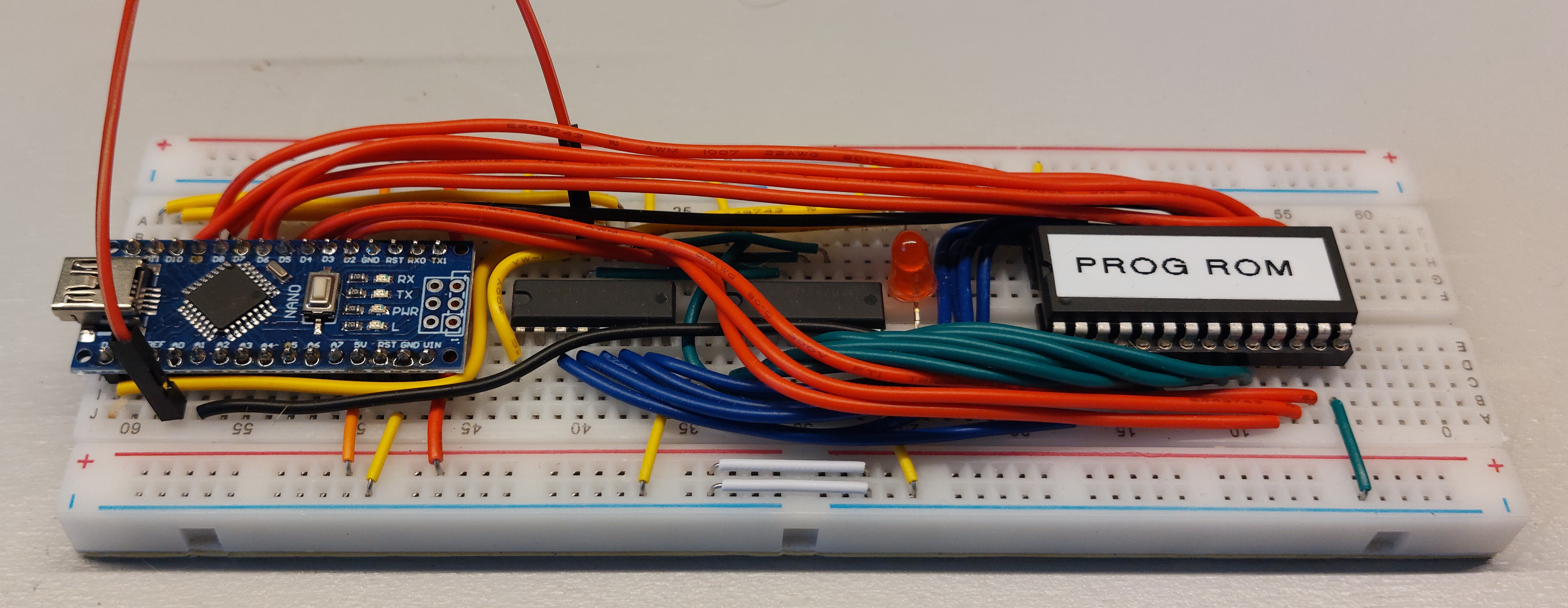
Given that there are four EEPROM chips embedded in the computer (one containing the program and three containing the microcode), we had to develop a toolkit for programming these. Specialized programmers can be pretty expensive and relatively hard to acquire, so an Arduino Nano was used to carry out that task. It waits for a serial connection and transfers incoming data byte by byte to the EEPROM chip. This serial connection is established by a Python script that accepts a binary blob and passes this on to the Arduino. The Python utility is called bflash (although it’s not really BF-specific); its source and the Arduino sketch can be found at https://github.com/jorenheit/bfcpu/tree/main/src/bflash. A schematic for the programmer hardware (Figure 34) is shown in Appendix Schematics.
Flashing the AT28C64B
The AT28C64B EEPROM chip is used for both microcode and program storage. A value can be written to a specific address using the following sequence of inputs:
Assert the value and address onto the data and address lines of the EEPROM.
Set WE (Write Enable) low and OE (Output Enable) high. Both of these pins are active low, so this puts the chip in write-mode.
Hold CE (Chip Enable) low for at least 100ns; we chose 1s because this is the smallest delay that can be performed using standard Arduino library functions.
Shift Register
Because of the large number of connections to the EEPROM chip (13 address lines, 8 data lines and 3 control lines), two shift registers (74HC595) were used to buffer the address and WE/OE control lines.
Microcode Compiler (Mugen)

Motivation
Initially, the binary images that were burnt onto the microcode EEPROM chips were generated using a simple Octave/MATLAB script. This meant that both the microcode and the logic to generate the images had to be expressed in this language. While this certainly worked (albeit a bit slowly), we felt the need to develop a more general approach to generating microcode images. To satisfy this need, Mugen was developed. It takes a file in which the microcode can be expressed intuitively and generates the binary images from it. The Mugen project can be found at https://github.com/jorenheit/mugen. The listing in Appendix Mugen Specification shows the contents of the Mugen specification file for this project.
File Structure
A Mugen file consists of five or six different sections in any order:
rom: specifies the ROM configuration of the system;signals: lists all the signals that make up the control word;opcodes: lists all the opcodes of the CPU and assigns numerical values to them;address: specifies how the microcode table address is formed from the opcode, cycle-count and flag-bits;microcode: specifies the control-sequences for each of the opcodes;macros(optional): lists common signal combinations that can be referred to by a single name in the microcode section (or within the macro section itself).
Emulation Framework (Rinku)

Before and during development of the physical system, a C++ framework was developed for emulating computational systems by defining modules and signals that connect them. Synapse-191 has been emulated cycle-accurately using this framework, which could then be debugged interactively to identify issues with the logic of the real-life computer. Mugen was used to generate C++ source code containing the lookup tables that are normally flashed to the EEPROM chips, such that the same .mu files could be used to drive the real system as well as the emulated one. The Rinku project can be found on GitHub at https://github.com/jorenheit/rinku/.