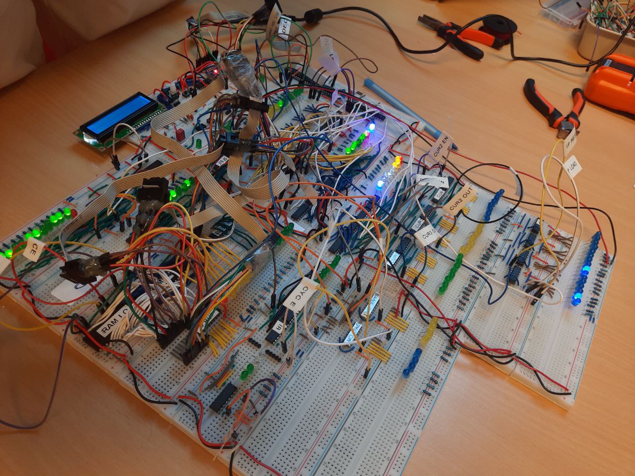
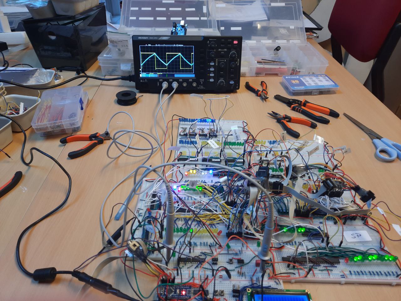
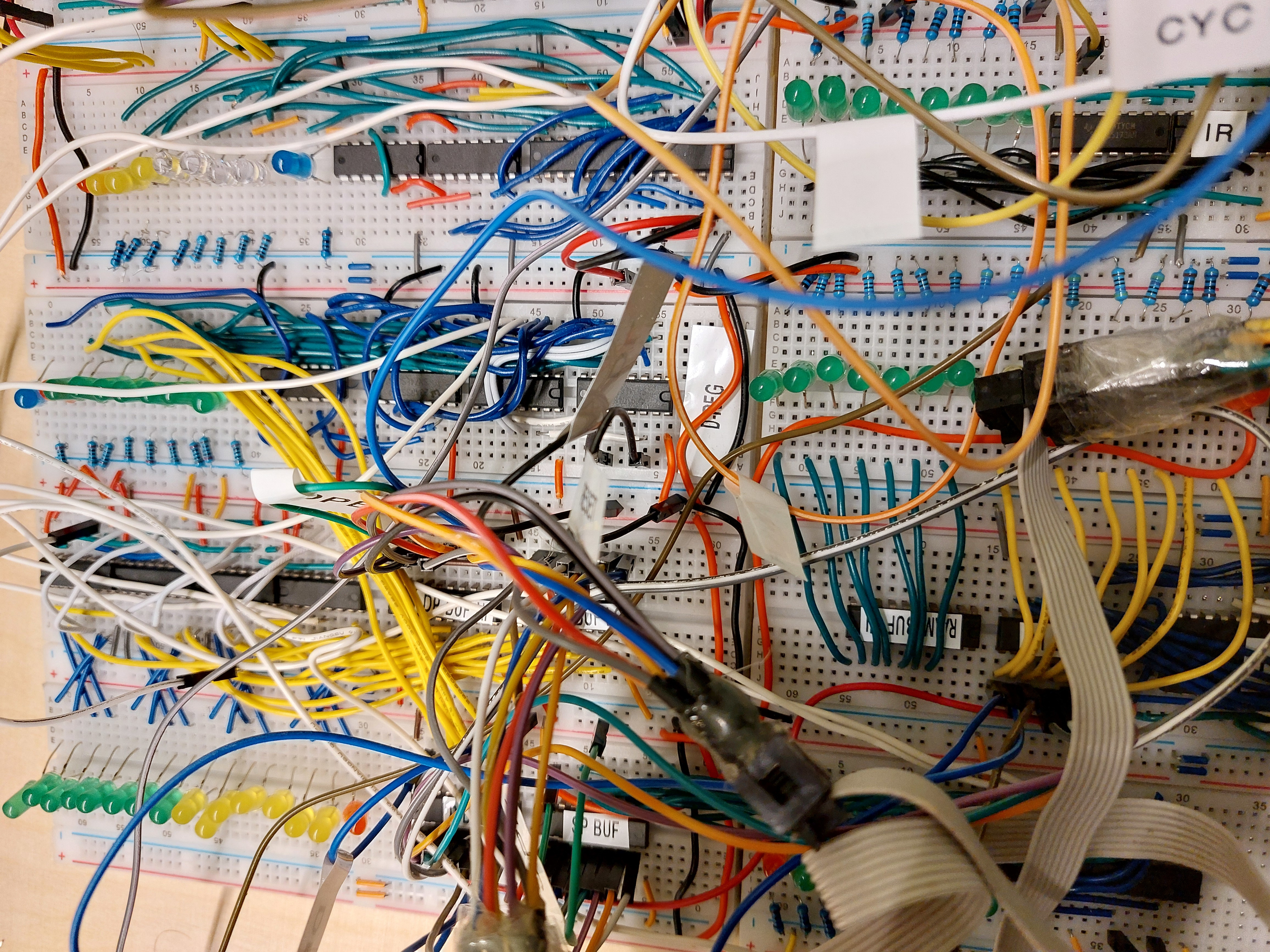
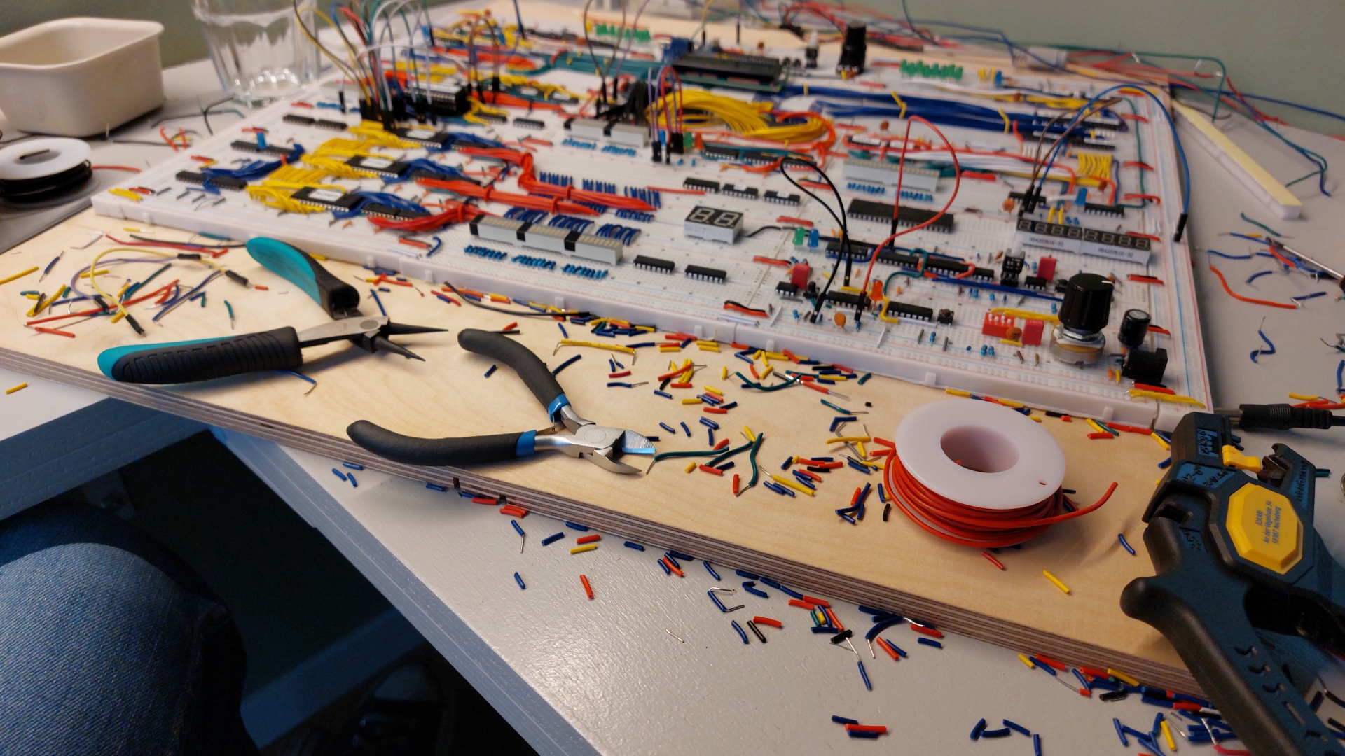
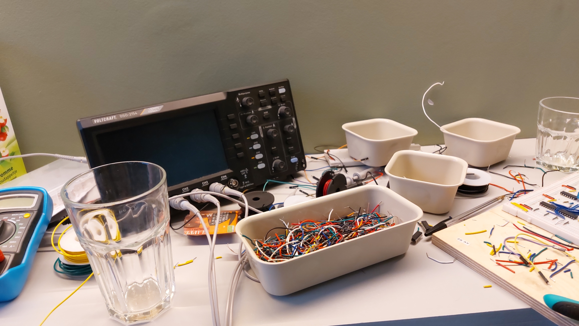
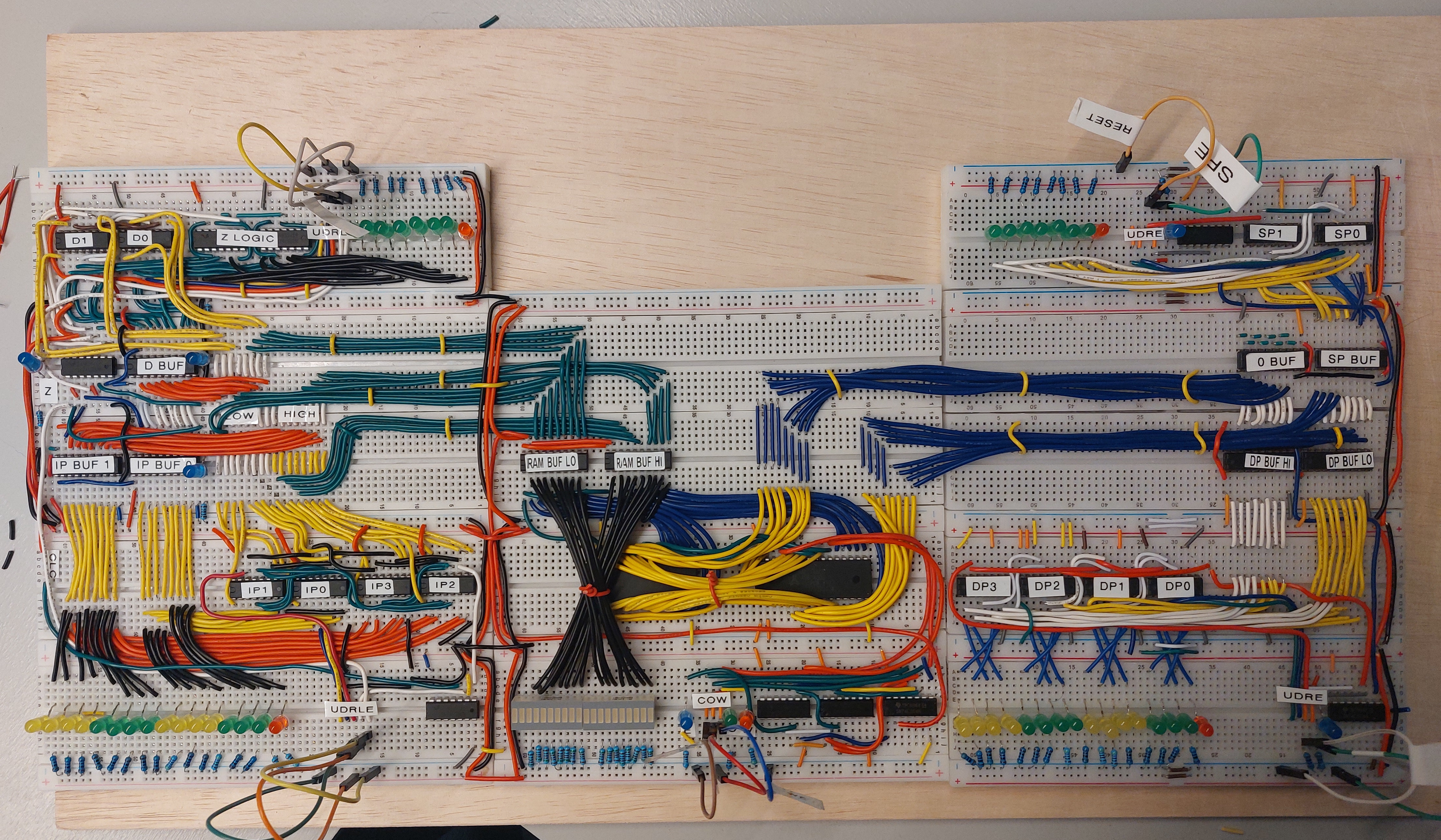
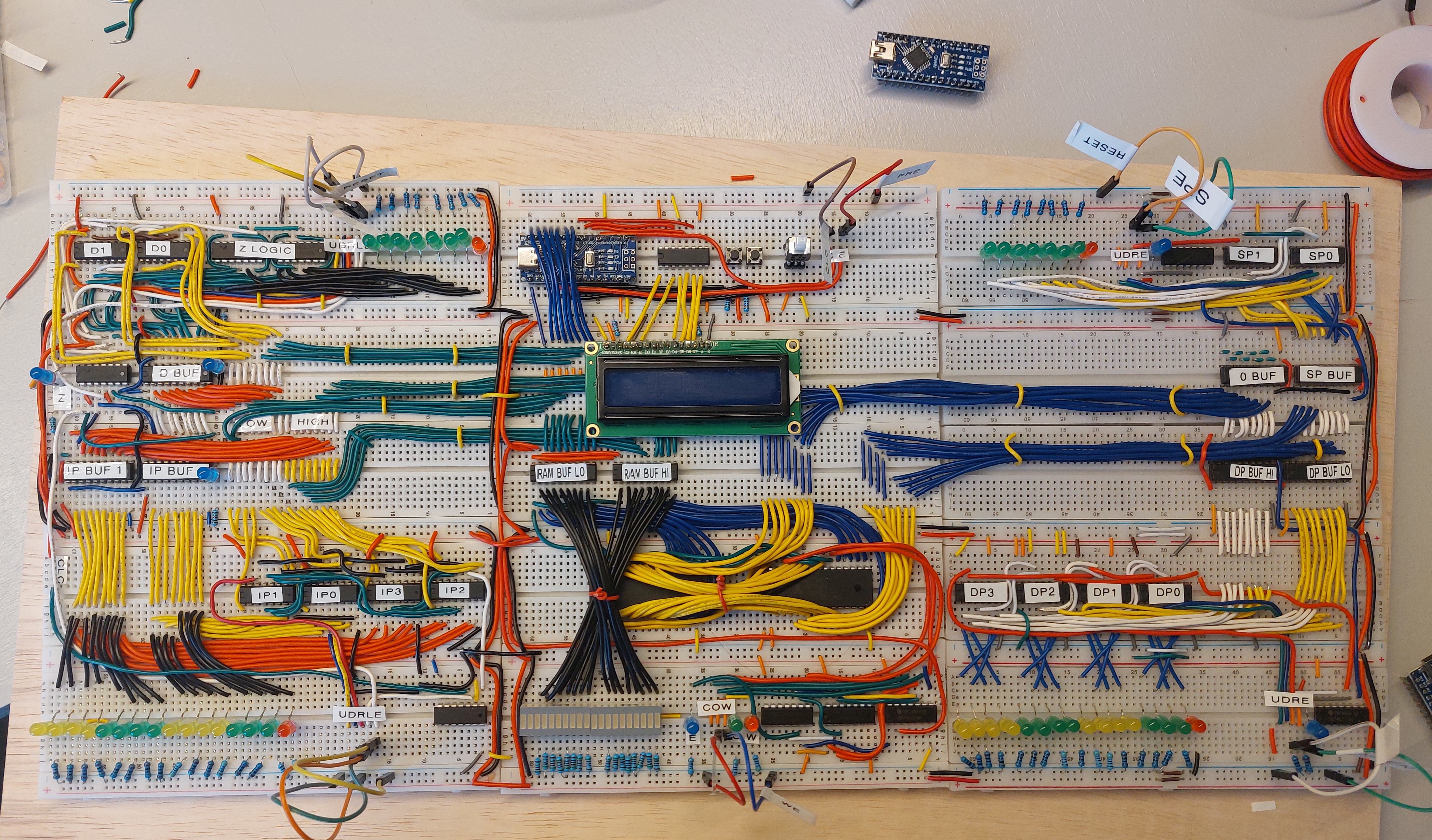
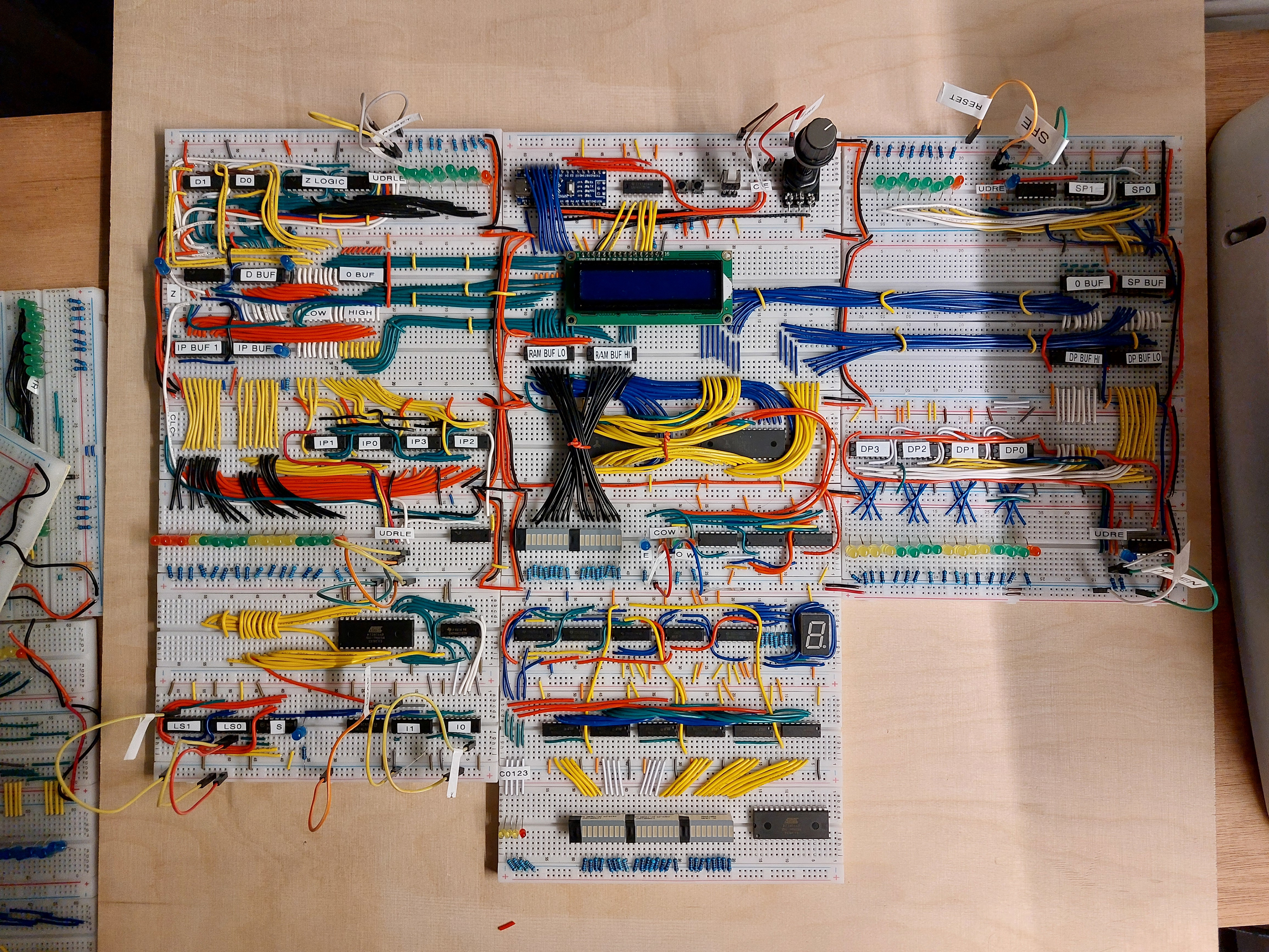
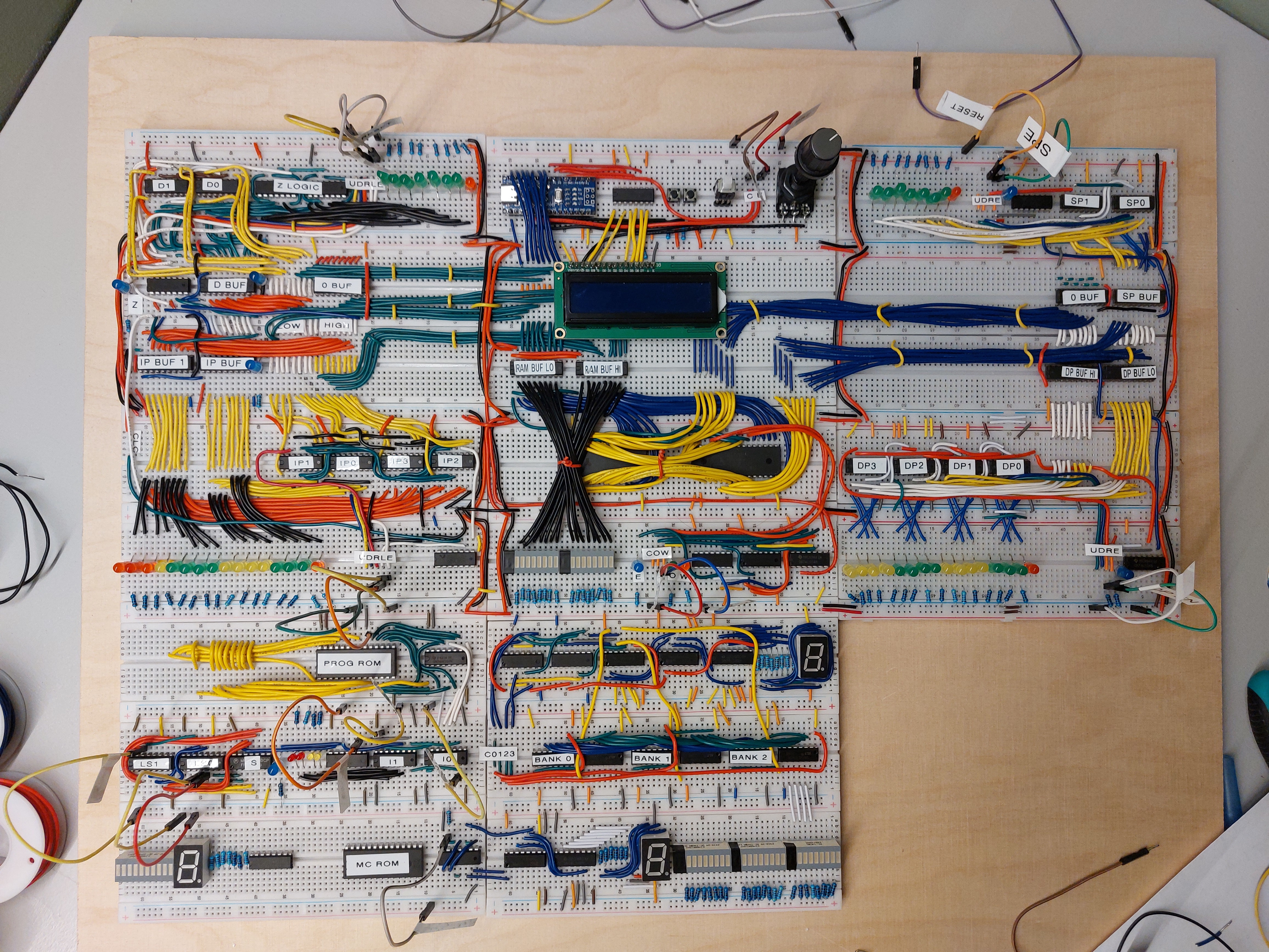
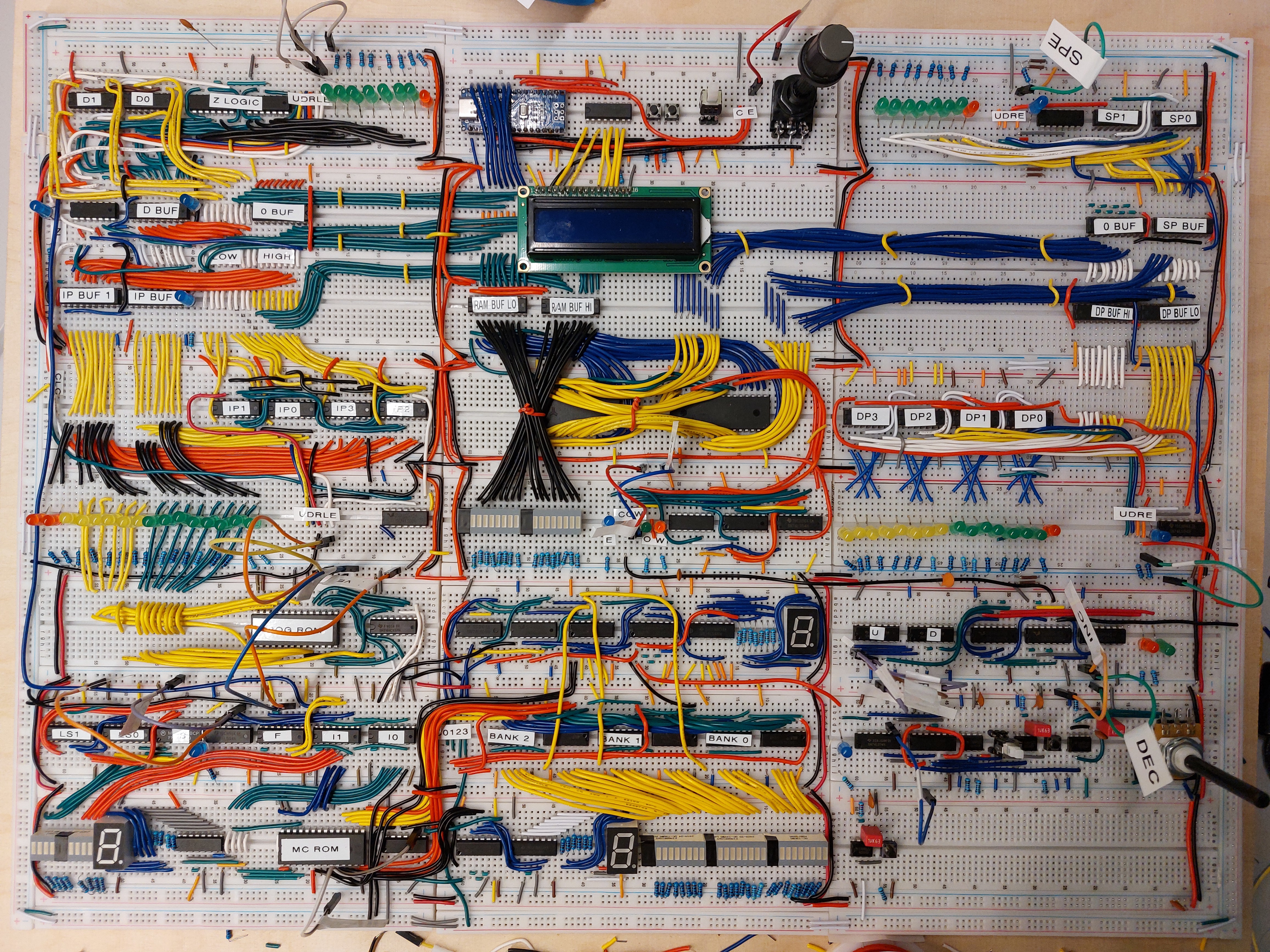
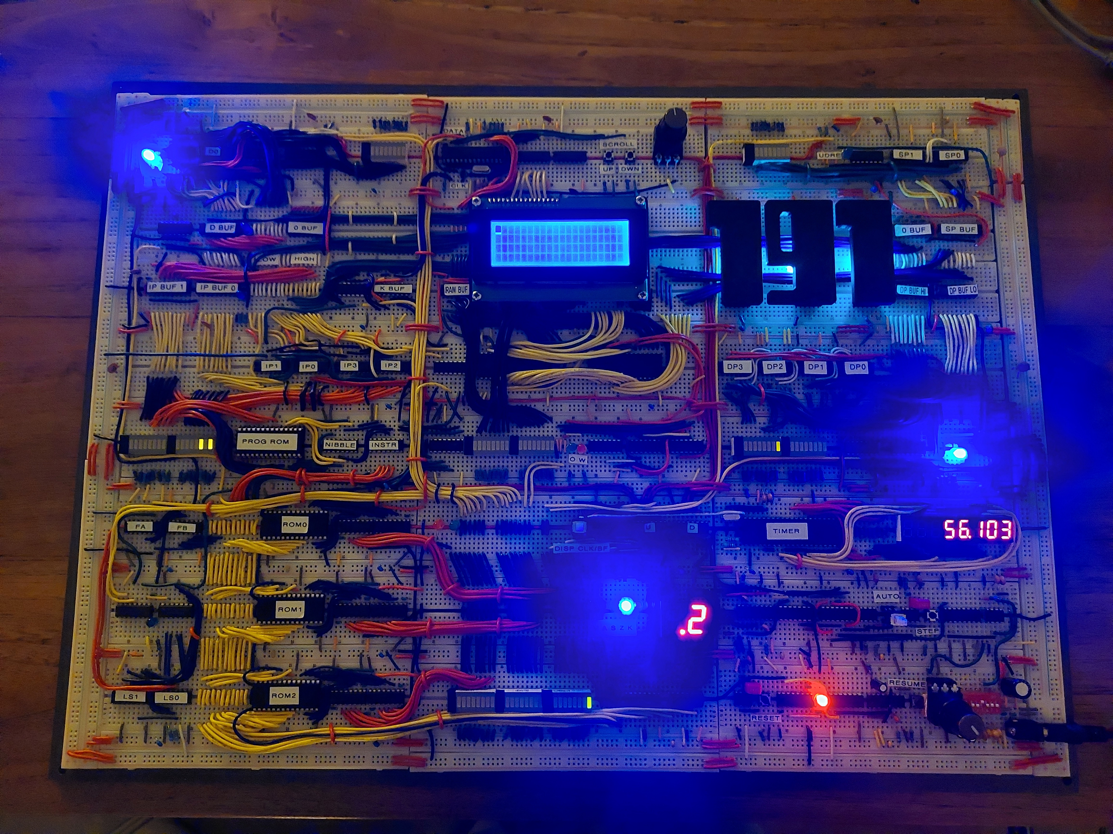
Figure 53. Early prototyping in 2024.Figure 54. Early prototyping in 2024.Figure 55. Early prototyping in 2024.Figure 56. Early prototyping in 2024.Figure 57. Wire stripping can quickly lead to a mess.Figure 58. A typical view when building and debugging the system.Figure 59. Registers and RAM first put together, the system starts to take shape.Figure 60. An early version of the IO module, including an Arduino Nano, was added to the system.Figure 61. The (segmented) control unit starts to take shape. The bottom-middle section contains the logic for sequentially fetching the three parts of the control word from different sections in the MC EEPROM chip.Figure 62. The (segmented) control unit starts to take shape even more. A display for showing the current instruction was added (7-segment display, bottom left).Figure 63. First (somewhat) working version of the system.Figure 64. Final build of the system, including 3D-printed parts and many pretty lights.